|
The Turn Of The Century Electrotherapy Museum http://www.electrotherapymuseum.com Tesla "Pancake Coils": Redefining Tesla Technologies |
|
The
Oscillation Transformer from
Thomas
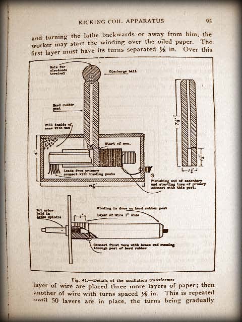
Stanley Curtis "High Frequency Apparatus" This coil is wound in a success of layers in flat or pancake form as its name implies. The wire is No. 30 D.C.C. and the insulating material between layers of wires is oiled paper 1 1/2 in. wide and .003 thick. The post shown in Fig. 41 is of hard rubber. While the rod is held in the chuck a ;4 in. hole is drilled clear through. The tail stock center is then brought up to bear in the hole to prevent chattering and the end of the post is finished off. A cut-off tool introduced at the correct position finishes the rubber rod. The hole at the base of the rod is to be tapped out 5/16-18. A length of brass rod is then forced in from the top of the post and cut off when it has entered to within 1 1/2 in. of the base. The top is threaded to enter a discharge ball and near the bottom a small hole is drilled through the hard rubber rod and into the brass to take an escutcheon pin which forms a means of connection. The rubber post is then to be screwed on to an arbor threaded 5/16-18 with a large disc of metal or wood between. Upon this rig, the pancake coil is to be wound. The winding may be done either in the lathe or, if none is available, in a simple, home-made winder. The starting end of the wire is soldered to the head of the escutcheon pin that makes connection with the central rod. Taking three turns of the oiled paper over the rubber post, and turning the lathe backwards or away from him, the worker may start the winding over the oiled paper. The first layer must have its turns separated 1/8 in. Over this layer of wire are placed three more layers of paper; then another of wire with turns spaced 1/8 in. This is repeated until 50 layers are in place, the turns being gradually placed closer together until, with the 50th layer, they are separated only 1/32 in. From this point on and until the 150th layer, which completes the coil, has been wound, the turns may be spaced about 32 to the inch. The layers should be but one inch in width in order that a margin of 1/4 in. may be left on either edge. The final layer of wire is to be covered with 10 layers of oiled paper, the end of the winding being brought out ready for connection with the primary. The primary consists of 10 turns of copper ribbon, 1 in. wide, wound spirally around the secondary pancake. Between the turns of the primary is a strip of corrugated board such as is used for packing purposes. The finishing end of the secondary is soldered to the starting end of the primary and at this point a length of flexible lamp cord connects to the junction of the two. The ten primary turns are then wound and a tap of lamp cord taken from the upper edge of each of the turns from the third to the tenth inclusive. This provides a means of varying the primary inductance while tuning the apparatus. The final primary turn is held mechanically by means of a wrapping of several layers of oiled paper; the latter may be shellacked in place. Removing the coil from the lathe, we now have the complete winding ready for impregnation with the compound already suggested for the condenser. The entire coil is to be immersed in the molten wax for several hours and, before its removal, the heat should be withdrawn in order that the mass may partially congeal. As the wax shrinks on cooling, it is essential that the substance be permitted to contract within the coil. While the winding is being treated, the worker may build the box that is to contain the oscillation transformer. The case may be square and deep enough to permit an inch of wax above and below the coil. It is obvious that the box must be wax-tight for the molted compound is to be poured into the container.
|
 |
 Reproduction "Kicking Coil" Portable X-Ray Coil - Inspired by Thomas Stanley Curtis and Frank S Betz |
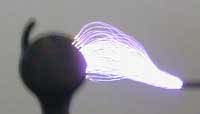
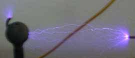
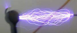
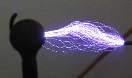
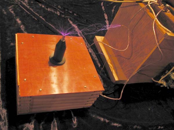 Testing of 3" Diameter Multilayered Pancake Coil with the "Behary Universal Tesla Coil Tuner" 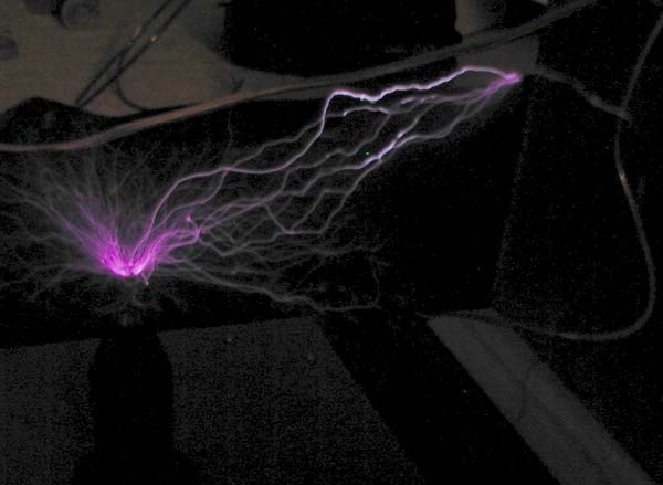 .75" High x 3" Diameter Coil yields over 4" Sparks at less than 100 watts 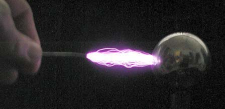 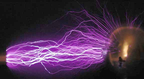 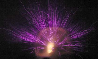 Testing a 10.75" Diameter Pancake Coil. Power supply is a standard "Violet Ray" circuit with two magnet coils wired in parallel. Power consumption is approx. 75 watts - 100 watts. Note the variance in the discharges when a Kicking Coil circuit is used as compared to a spark gap. |
 |